After pondering the issue for years, I have came to a big decision about the era my model will represent – the 1980s, as I remember nostalgically from those Christmas kids parties of my childhood. This is before big changes were made in the 1990s but after the major project of the W407 computer room and its rooftop penthouse. The changes in the 1990s/early 2000s include:
- moving out of North Block;
- Staff Restaurant major refurbishment;
- replacement of the Photographic/PLC area with the Business Centre;
- new Reception area;
- general refurbishment of most office spurs;
- refurbishment of large areas of the 1st/2nd and 4th floor of West Block; and
- Services Block – replacement of old workshops with Nursery and maintenance staff offices.
The refurbishment projects mentioned above did greatly improve the working environment and extended the building’s lifecycle but the original version is more authentic to the original design and I also have no detailed plans or sections etc of the new areas although a lot of of the photos from the Wiki that myself and Ian Corps took. I could always create an alternative version of the model with the new stuff although that would not be that accurate. Whereas I have a full set of drawings for the original design and also the very useful Maybush construction photos. Much of the behind the scenes plant rooms and penthouses were pretty much unchanged from the late 60s.
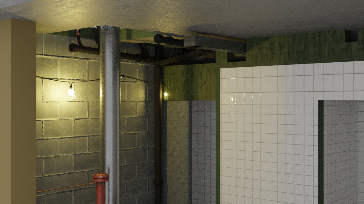
Work has continued on A core and the toilets area, mainly installation of the larger pipes from the Subway rising through the floors and drainage pipes down through the foundations and also ducts from the rooftop penthouse.
This matter is massively complicated by the fact that the drawings for drainage and cold water supply do not show the positions of hot water pipes or ducts and the mechanical and electrical (M&E) drawings do not show the positions of drainage or cold water pipes – they are completely seperate. I would have thought the drainage plans are older as they had to be embedded deep into the foundations but the structural engineering diagrams don’t show drainage foundation holes either, despite showing the holes at higher levels. The lack of photos of these areas also does not help. This means I have used what I call ‘artistic licence’ – such fun – in guessing the location of things.
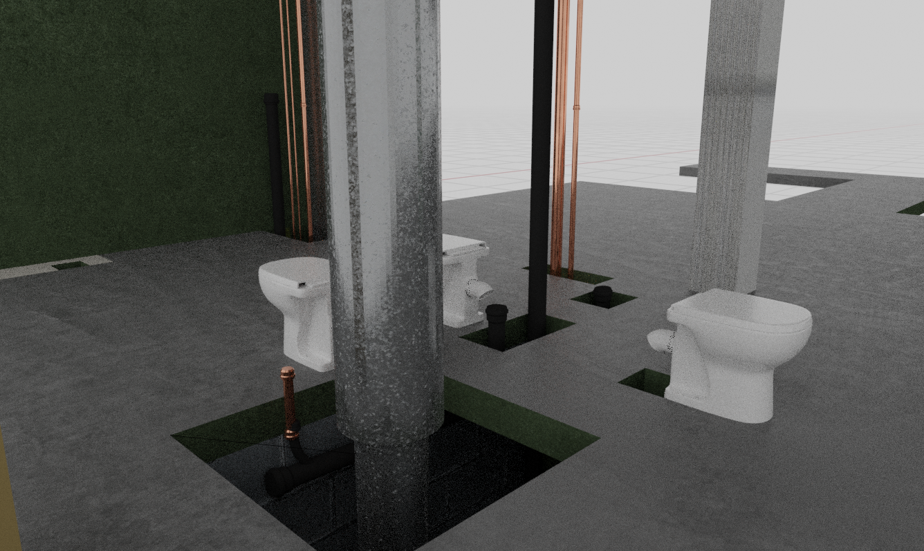
Most of the drainage pipes for WCs, urinals and drinking fountains are in place now but the smaller basin waste pipes need doing along with their vent pipes. I have managed to find a WC pan online that looks reasonably good but still need to find a decent basin and old-fashioned urinal – I will probably try and reproduce the basin in my bathroom as it is rather old and looks the same shape as the ones on the OS drawings. There are also only one photo I have seen of the original toilets and that is just the basin. Obviously not something anyone would take photos of!
The Pipe Systems add on I bought for Blender has enabled everything to be modelled in detail, as the soil pipes have different joints (not flanged like the heating pipes). The other connector types also work well for the smaller copper pipes with welded joints.
I had always assumed that the cold water serving the main core risers came from the Subway via the booster pump room below the Restaurant but the supply system is rather more complex, there was a ‘ring main’ running round the main buildings with spurs off to each core and then a ‘rising main’ up to the Penthouse, where it branched off into a drop to the two drinking water fountain risers (one for each lav) and a large rooftop tank. The sink/WC/urinals on each floor were fed by a drop down from that tank.
I was a little surprised to see that all the toilets (five per floor) ultimately led to one standard size 4 inch soil pipe, I would have thought there was more than one or a larger size.

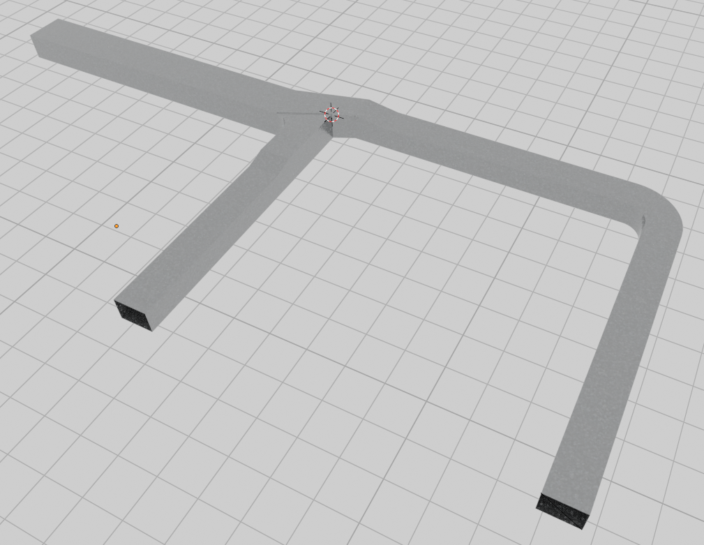
Another significant achievement was the creation of the rectangular toilet extract ducts and one of the circular supply ducts. These ran along the rooftop behind the parapets from E core penthouse although I have only created the A core riser so far. The actual duct layout is complex and a different diameter on each floor.
I mainly going to create all these pipes etc for one floor of each core, otherwise it will become too complex. The other floors will just have the structural walls but the large rising pipes spanning multiple floors will remain.
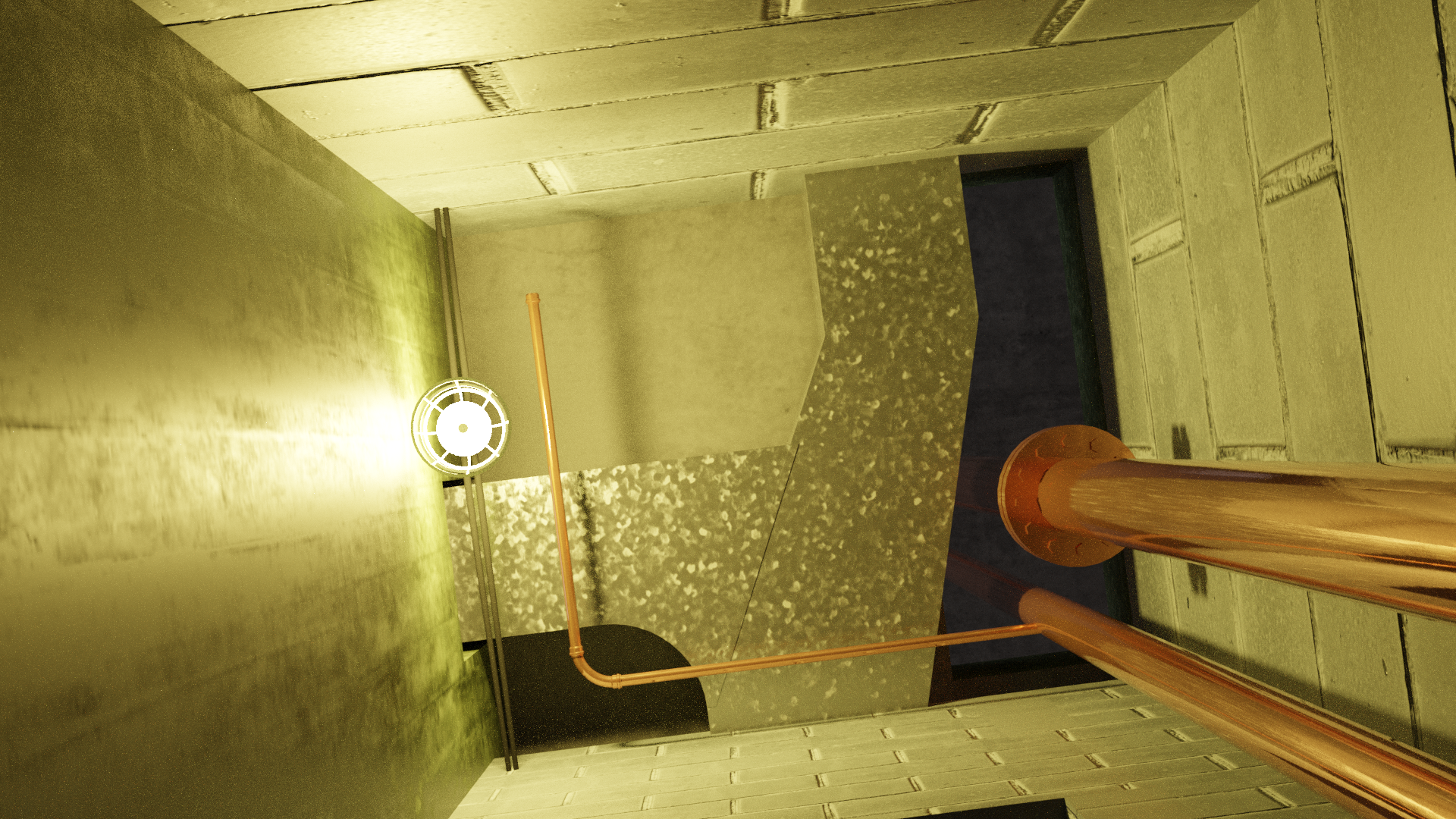
Another good point about this area is the fact that the rooms are very small so getting a realistic view for the render cameras is not easy – I am tempted to do an isometric, what I call an ‘exploded view’ of the infrastructure without the walls.
Next steps – my annual Christmas render for Facebook will take up the next couple of weeks so I will come back to the A Core services. What still needs to be done here?
- Flushing cisterns – basically just a rectangular tank much the same as a domestic one. I was surprised to find little in the way of more detailed 3D models so will probably do a simple one myself.
- Urinals and basins, and their pipes.
- Drinking fountains – I am not sure what these looked like so will probably amend the ones I made for the Staff Restaurant servery.
- Hot water service (HWS) pipes – partially in place.
- 2 inch heating main pipes serving offices
- And the ducts they ran alongside through the offices under windows.
- Staying with the supply ducts, the complex connection between their riser and each floor.
- The natural progression from this is A Core penthouse and its water tanks and pipes, as well as the toilet extractor fans. There is a lot of structural work needed first though, from the penthouse walls and lift shafts and plinth for the water tanks.